User Manual 3.3 Frames : Différence entre versions
(→Javadoc) |
(→Package Overview) |
||
| Ligne 30 : | Ligne 30 : | ||
The following UML diagram presents the main packages and classes of frames in Patrius. | The following UML diagram presents the main packages and classes of frames in Patrius. | ||
| − | [[ | + | [[File:frames-class-diagram.png|700px]] |
The frames that are not managed by the configuration are given hereunder : | The frames that are not managed by the configuration are given hereunder : | ||
Version du 27 février 2018 à 08:16
Sommaire
Introduction
Scope
In Orekit, a frame is represented by the class Frame. The different frames are organized as a tree whose root is the Geocentric Celestial Reference Frame. A frame is defined by a transformation with respect to its parent. A frame factory enables us to build easily some current frames such as GCRF, EME2000, ITRF... Models and data defining transformations between frame is defined in [FDY_FRCON_Home Frames configuration]
Javadoc
The frames are available in the package org.orekit.frames of OREKIT.
| Library | Javadoc |
|---|---|
| Orekit | Package org.orekit.frames |
| Orekit | Package org.orekit.frames.transformations |
Links
- Orekit frames architecture (some of this information may be obsolete)
Useful Documents
None as of now.
Package Overview
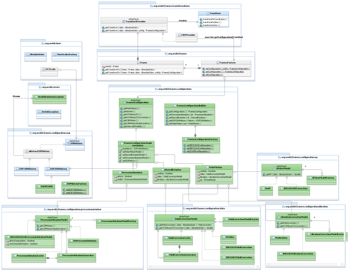
The following UML diagram presents the main packages and classes of frames in Patrius.
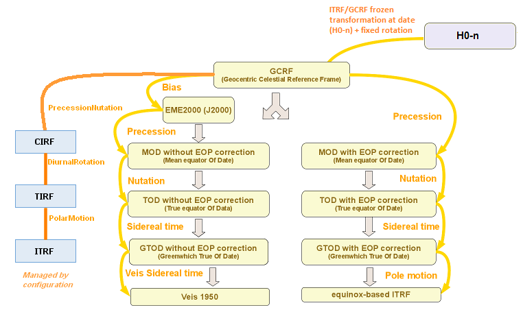
The frames that are not managed by the configuration are given hereunder :
Features Description
Frames
The following frames are available in PATRIUS:
- Reference frames :
- GCRF,
- CIRF,
- TIRF,
- ITRF,
- EME 2000,
- MOD with and without EOP corrections,
- TOD with and without EOP corrections,
- GTOD with and without EOP corrections,
- and more ...
- Local orbital frames
- Vehicule frame (see AttitudeFrame in the [ATT_ALW_Home attitude laws] section)
- Topocentric frames
To use any of the reference frames, the user must use the FramesFactory like so :
Frame eme2000 = FramesFactory.getEME2000();
PATRIUS implements a frame configuration mechanism. To use it, see the [FDY_FRAME_Home#HTheFramesConfiguration Frames Configuration] section in this page.
See FramesFactory javadoc for a complete list of public methods.
Topocentric frame
A topocentric frame can be instantiated with the class TopocentricFrame, in Orekit.frames. This class is based on the BodyShape and GeodeticPoint classes.
TopocentricFrame
This class provides two constructors. The simplest one returns an East oriented topocentric frame. The second one, that works with an angle, returns a North oriented topocentric frame if the angle is 0, or an image of this frame through the rotation around the zenith direction of the given angle (counterclockwise).
// Reference frame = ITRF
Frame frameITRF = FramesFactory.getITRF();

// Elliptic earth shape
OneAxisEllipsoid earthSpheric = new OneAxisEllipsoid(6378136.460, 0., frameITRF);

// Geodetic point at which to attach the frame
GeodeticPoint point = new GeodeticPoint(FastMath.toRadians(0.), FastMath.toRadians(30.), 0.);

// Build the east frame
TopocentricFrame topoEast = new TopocentricFrame(earthSpheric, point, "lon 30 lat 0");

// Build a frame rotated by 30° from the North frame
TopocentricFrame topo30 = new TopocentricFrame(earthSpheric, point, FastMath.toRadians(30.), "lon 30 lat 0");
It can provide a number of directions, such as West, North or Nadir. It provides methods that compute elevation, azimuth and the range of a point located by a cartesian vector.
// get the zenith or the Nadir
Vector3D north = topoEast.getZenith();
Vector3D nadir = topoEast.getNadir();

// compute the azimuth of a position
Vector3D position = new Vector3D(1.0, 2.0, 3.0);
double azimuth = topo30.getAzimuth(position, earthSpheric.getBodyFrame(), date);
Finally, being a Frame, it can be used to automatically transform a position/velocity to any frame (the inverse is also possible).
//get the transformation from the topocentric East to the ITRF
Transform eastTOitrf = topoEast.getTransformTo(frameITRF, AbsoluteDate.FIFTIES_EPOCH_UTC);

//apply the transformation
PVCoordinates pointPVeast= new PVCoordinates(new Vector3D(0.,-1., 1), Vector3D.ZERO);
PVCoordinates pointPVitrf= eastTOitrf.transformPVCoordinates(pointPVeast);
These examples are available in the TopocentricFrameTest class. Other examples can be found in the tests.
TopocentricCoordinates
The topocentric coordinates are defined by the elevation, the azimuth and the distance from the center of the local topocentric frame [R2].
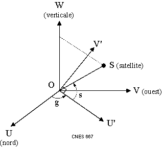
The azimuth is the angle between the local North and the projection of the line which joins the center of the topocentric frame and the satellite in the horizontal plane. This angle ranges from 0 to 2[math]\pi[/math]. This angle is oriented by the axis opposite to the Zenith. On the figure, the angle g is called the bearing, it is linked to the azimuth by : g = 2[math]\pi[/math]- azimuth.
The elevation is the angle between the line which joins the center of the topocentric frame and the satellite and the projection of this line in the horizontal plane. This angle ranges from-[math]\pi[/math]/2 to [math]\pi[/math]/2. This angle is oriented by the image of the West axis by the rotation of angle azimuth and around Zenith axis. On the figure, s is the elevation angle.
If the elevation equals [math]{\pi\over2}[/math] or [math]-{\pi\over2}[/math], the azimuth is undefined.
The object TopocentricCoordinates contains also the first derivatives of these elements (elevation rate, azimuth rate and range rate).
We can transform the position of the satellite expressed in Cartesian coordinates into TopocentriCoordinates and vice versa.
We can also transform PVCoordinates into TopocentricCoordinates and vice versa.
// North topocentric frame
final GeodeticPoint point = new GeodeticPoint(FastMath.toRadians(43.604482), FastMath.toRadians(1.443962), 0.);
final TopocentricFrame topoNorth = new TopocentricFrame(earthSpheric, point, 0., "north topocentric frame");
final AbsoluteDate date = new AbsoluteDate(new DateComponents(2008, 04, 07),
                                           TimeComponents.H00,
                                           TimeScalesFactory.getUTC());
// Topocentric coordinates
TopocentricPosition topoCoord = new TopocentricPosition(FastMath.acos(FastMath.sqrt(2. / 3.)),
                                                              FastMath.toRadians(315),
                                                              FastMath.sqrt(3));
// Cartesian coordinates (position only)
Vector3D position = topoNorth.transformFromTopocentricToPosition(topoCoord);
// North topocentric frame
final GeodeticPoint point = new GeodeticPoint(FastMath.toRadians(43.604482),FastMath.toRadians(1.443962), 0.);
final TopocentricFrame topoNorth = new TopocentricFrame(earthSpheric, point, 0., "north topocentric frame");
final AbsoluteDate date = new AbsoluteDate(new DateComponents(2008, 04, 07),
                                           TimeComponents.H00,
                                           TimeScalesFactory.getUTC());
// Cartesian coordinates (position only)
Vector3D position = new Vector3D(1,1,1);
// Topocentric Coordinates
TopocentricPosition topoCoord = topoNorth.transformFromPositionToTopocentric(position, topoNorth, date);
CardanMounting
The Cardan mounting is defined by two angles (X and Y) and the distance from the center of the local topocentric frame [R2].
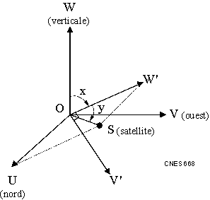
The X angle is the angle between the Zenith and the projection of the line which joins the center of the topocentric frame and the satellite in the vertical plane (plane defined by the Zenith and the West axis). This angle ranges from-[math]\pi[/math] to [math]\pi[/math]. This angle is oriented by the South axis. On the figure, x is the X angle.
The Y angle is the angle between the line which joins the center of the topocentric frame and the satellite and the projection of this line in the vertical plane (plane defined by the Zenith and the West axis). This angle ranges from-[math]\pi[/math]/2 and [math]\pi[/math]/2. It is oriented by the image of the West axis by the rotation of angle X and around North axis. On the figure, y is the Y angle.
If the Y angle equals [math]\pi[/math]/2 or-[math]\pi[/math]/2, the X angle is undefined.
The object CardanMounting contains also the first time derivatives of these elements (X angle rate, Y angle rate and range rate).
We can transform the position of the satellite expressed in Cartesian coordinates into CardanMounting and vice versa.
We can also transform PVCoordinates into cardanMounting and vice versa.
// North topocentric frame
final GeodeticPoint point = new GeodeticPoint(FastMath.toRadians(43.604482), FastMath.toRadians(1.443962), 0.);
final TopocentricFrame topoNorth = new TopocentricFrame(earthSpheric, point, 0., "north topocentric frame");
final AbsoluteDate date = new AbsoluteDate(new DateComponents(2008, 04, 07),
TimeComponents.H00,
TimeScalesFactory.getUTC());
// Cardan mounting
CardanMountPosition cardanCoord = new CardanMountPosition(FastMath.toRadians(45),
                                                 FastMath.acos(FastMath.sqrt(2. / 3.)),
                                                 FastMath.sqrt(3));
// Cartesian coordinates (position only)
Vector3D position = topoNorth.transformFromCardanToPosition(cardanCoord);
// North topocentric frame
final GeodeticPoint point = new GeodeticPoint(FastMath.toRadians(43.604482), FastMath.toRadians(1.443962), 0.);
final TopocentricFrame topoNorth = new TopocentricFrame(earthSpheric, point, 0., "north topocentric frame");
final AbsoluteDate date = new AbsoluteDate(new DateComponents(2008, 04, 07),
                                           TimeComponents.H00,
                                           TimeScalesFactory.getUTC());
// Cartesian coordinates (position only)
Vector3D position = new Vector3D(1,1,1);
// Cardan mounting
cardanCoord = topoNorth.transformFromPositionToCardan(position, topoNorth, date);
"H0- n" frame
The "H0- n" frame is a pseudo-inertial frame; its parent frame is the GCRF. It uses the frozen transformation of the ITRF with respect to the GCRF frame at the date "H0- n", combined with a rotation by a fixed angle around the Z axis of the ITRF frame.
Getting Started
TBD
Contents
Interfaces
Classes
|=(% colspan="3" %)Class|=(% colspan="6" %)Summary|=(% colspan="1" %)Javadoc |(% colspan="3" %)FactoryManagedFrame|(% colspan="6" %) Base class for the predefined frames that are managed by FramesFactory.|(% colspan="1" %)... |(% colspan="3" %)Frame|(% colspan="6" %)Tridimensional references frames class.|(% colspan="1" %)... |(% colspan="3" %)FramesFactory|(% colspan="6" %}Factory for predefined reference frames.|(% colspan="1" %)... |(% colspan="3" %)HelmertTransformation|(% colspan="6" %)Transformation class for geodetic systems.|(% colspan="1" %)... |(% colspan="3" %)LocalOrbitalFrame|(% colspan="6" %)Class for frames moving with an orbiting satellite.|(% colspan="1" %)... |(% colspan="3" %)SpacecraftFrame|(% colspan="6" %)Spacecraft frame|(% colspan="1" %)... |(% colspan="3" %)TopocentricFrame|(% colspan="6" %)The topocentric frame.|(% colspan="1" %)... |(% colspan="3" %)Transform|(% colspan="6" %)Transformation class in three dimensional space.|(% colspan="1" %)... |(% colspan="3" %)H0MinusNProvider|(% colspan="6" %)Provider for the "H0-n" frame.|(% colspan="1" %)... |(% colspan="3" %)FrameConvention|(% colspan="6" %)Enumeration of all frame conventions used in Patrius.|(% colspan="1" %)...
Tutorials
Tutorial 1
TBD
Tutorial 2
TBD
 Tips & Tricks
IERS frames transformations
This chapter sums up the up and downsides of the use of the IERS frames in Orekit. Its purpose is to help the user avoid some traps and know what to expect as to the numerical precision of the computations. Further explanations about the IERS frames can be found on the IERS website[R1].
Tips
One can compute the transformations between two frames with a specific frames configuration passed as a parameter as opposed to the Orekit frames configuration (that is obtained with the FramesFactory.getConfiguration() method). Given a date and a user specific config, the method to call is :
frame1.getTransformTo(frame2, date, config);
One can also compute the jacobian matrix of the conversion between two frames. Given a date epoch, the jacobian matrix of the conversion from frame1 to frame2 is computed by the method getTransformJacobian called by :
frame1.getTransformJacobian(frame2, epoch);
Traps
The first thing to check when working with IERS frames is the presence of the Earth Orientation Parameters bulletins it requires. Indeed, if the c04 bulletins of the correct year cannot be found in the data, Orekit will use the ones stored internally to compute the transformations. To be sure that Orekit will use the good files, the user has first to point out the directory which contains these files. The fact that it doesn't warn the user that it does not have the parameters for the time of the simulation may lead to error, and thus the deviation compared to a reference could be enormous without the user being aware. One more thing to know about these bulletins is that they have to be continuous, meaning that the transformation won't work (and will throw an exception) if there are missing years or month in the files.
Make sure to use IAU 2000 EOP data, otherwise nutation corrections are null.
Usage of Frames
The methods to be used in order to instanciate the IERS Frames are :
- FramesFactory.getGCRF()
- FramesFactory.getCIRF()
- FramesFactory.getTIRF()
- FramesFactory.getITRF()


