« User Manual 4.0 Assemblies in PATRIUS: Presentation » : différence entre les versions
Aucun résumé des modifications |
|||
| Ligne 9 : | Ligne 9 : | ||
The main vehicle objects are available in the package <code>fr.cnes.sirius.patrius.assembly</code> | The main vehicle objects are available in the package <code>fr.cnes.sirius.patrius.assembly</code> | ||
|=Library| | {| class="wikitable" | ||
|Patrius |[{{PathCurrentJavaDoc}}/fr/cnes/sirius/patrius/assembly/package-summary.html Package fr.cnes.sirius.patrius.assembly] | |- | ||
! scope="col"| Library | |||
! scope="col"| Javadoc | |||
|- | |||
|Patrius | |||
|[{{PathCurrentJavaDoc}}/fr/cnes/sirius/patrius/assembly/package-summary.html Package fr.cnes.sirius.patrius.assembly] | |||
|} | |||
=== Links === | === Links === | ||
Version du 21 février 2018 à 13:29
Introduction
Scope
This chapter presents the global architecture of the assembly: its decomposition in parts and the notion of “properties” of those parts. These are only the main principles of the theme. Other chapters are dedicated to the assembly building and use with code samples.
Javadoc
The main vehicle objects are available in the package fr.cnes.sirius.patrius.assembly
| Library | Javadoc |
|---|---|
| Patrius | Package fr.cnes.sirius.patrius.assembly |
Links
None as of now.
Useful Documents
None as of now.
Package overview
Main principles :
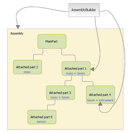
- An assembly is described by its sub parts (and can be made of only one).
- Each of these parts is definied by a name, a frame to know its position and orientation at any time, and a list of properties.
- The first created part is the "main part". Its associated frame defines the "main frame" of the vehicle.
- The assembly contains only information : it does not act as physical models (force computations for the spacecraft,...) and implements no complex algorithm. "Models" objects are used for this purpose.
- The assembly's creation is made through a "builder" object.

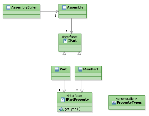
Classes of the package :
- The builder allows the user to instantiate their own assembly, building it step by step (see "Building the assembly").
- The assembly contains several parts , of the IPart type : one "MainPart" and some "Part" objects.
- The parts contain "properties" of the "IPartProperty" type.
- Each PartProperty is associated to a "PropertyType" that allows the user to add only one property of a certain type to a particular part.

Features Description
The tree of parts
Each Part is associated to a frame, which is defined relatively (position and orientation) to the frame of the parent part. The “main part” is associated to the main frame, that has no parent unless the vehicle is linked to the main tree of frames.
Part Properies
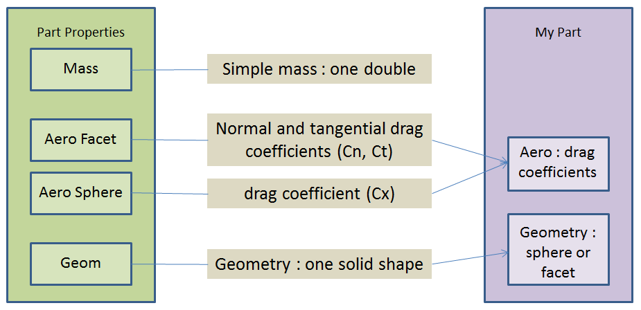
Each part has a list of properties that can be chosen arbitrarily amongst the ones available (e.g. mass, geometry, drag coefficient). The design of the Assembly package allows easy additions of new properties.
To ensure that a property of a particular type is added only once, a "Property type" list exists : different properties can be of a same "type" (for examples two ways of describing the drag coefficients).

Models
The physical models (such as forces computations on a spacecraft) are not part of the assembly package.
An assembly does not contain complex algorithm, it is only a description. A model shall be coded in a dedicated class, using if necessary an assembly to get its features.
This way, it is easy to create models implementing existing interfaces, or to create new models and interfaces

Available models
Here is a summary of available models, what they stand for, and the properties needed on the assembly parts for the model to work :
|= Model |= Ability |= Properties |AeroModel | Acceleration due to atmospheric drag | At least one part with MASS, AERO_FACET or AERO_SPHERE |DirectRadiativeModel | Acceleration due to radiation pressure | At least one part with RADIATIVE, MASS and either RADIATIVE_FACET or RADIATIVE_SPHERE |InertiaComputedModel | Inertia model for the assembly | INERTIA (note : INERTIA property provides its own mass) |InertiaSimpleModel | Inertia model provided by user | No assembly required |MassModel | Mass of the assembly | MASS (not required : if no part has a MASS property, total mass will be zero, and valid) |RediffusedRadiativeModel | Acceleration due to rediffused radiation | At least one part with MASS and either RADIATIVE_FACET or RADIATIVE_SPHERE, and also with RADIATIVE if albedo is enabled in the model, or RADIATIVEIR if infrared is enabled in the model |RFLinkBudgetModel | Accounting of all of the gains and losses from the transmitter (the satellite), through the medium, to the receiver (the ground station) | RF for the part identified as the antenna |SensorModel | Geometric properties of a given sensor (target visibility, masking, inhibition...) | SENSOR for the part identified as a sensor, GEOMETRY for the masking parts
For a model to work, it needs an assembly providing parts with the right properties. This is done by building a suitable assembly, as described in the [SPC_VBU_Home "Building and using an assembly"] chapter.