User Manual 3.4.1 Parallelepipeds
Aller à la navigation
Aller à la recherche
Definition
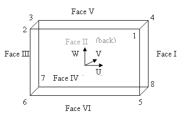
The parallelepipeds are rectangles defined in a 3D space by their centre and a local orthogonal frame (U, V, W).
- The normalized U vector defines the "length" direction
- The normalized V vector defines the "width" direction
- The normalized W vector defines the "height" direction
The four corners and faces can be retrieved in the following orders :

Implementation
The Parallelepiped object implements the SolidShape interface. Please refer to the Parallelepiped javadoc for a complete list of public methods.
Instantiation
The parallelepiped object is built from a centre (Vector3D), two vectors (Vector3D) to describe its orientation, and three dimensions :
Vector3D center = new Vector3D(1.0, 1.0, 1.0);
Vector3D uVector = new Vector3D(1.0, 1.0, 0.0);
Vector3D inputvVector = new Vector3D(-5.0, 1.0, 0.0);
Parallelepipedparallelepiped= new Parallelepiped(center, uVector, inputvVector, 4.0, 6.0, 2.0);
The local frame of the plate is build from the two orientation vector :
- U is the first once normalized (uVector)
- V is the vector computed to be orthogonal to U in the plane define by the two given vectors, in the direction of inputvVector.
- W is computed by cross product of U and V
Usage
Please refer to the [MAT_GEO_Home#HInteractions Interactions with other geometrical objects section] for methods inherited from the Shape interface.